|
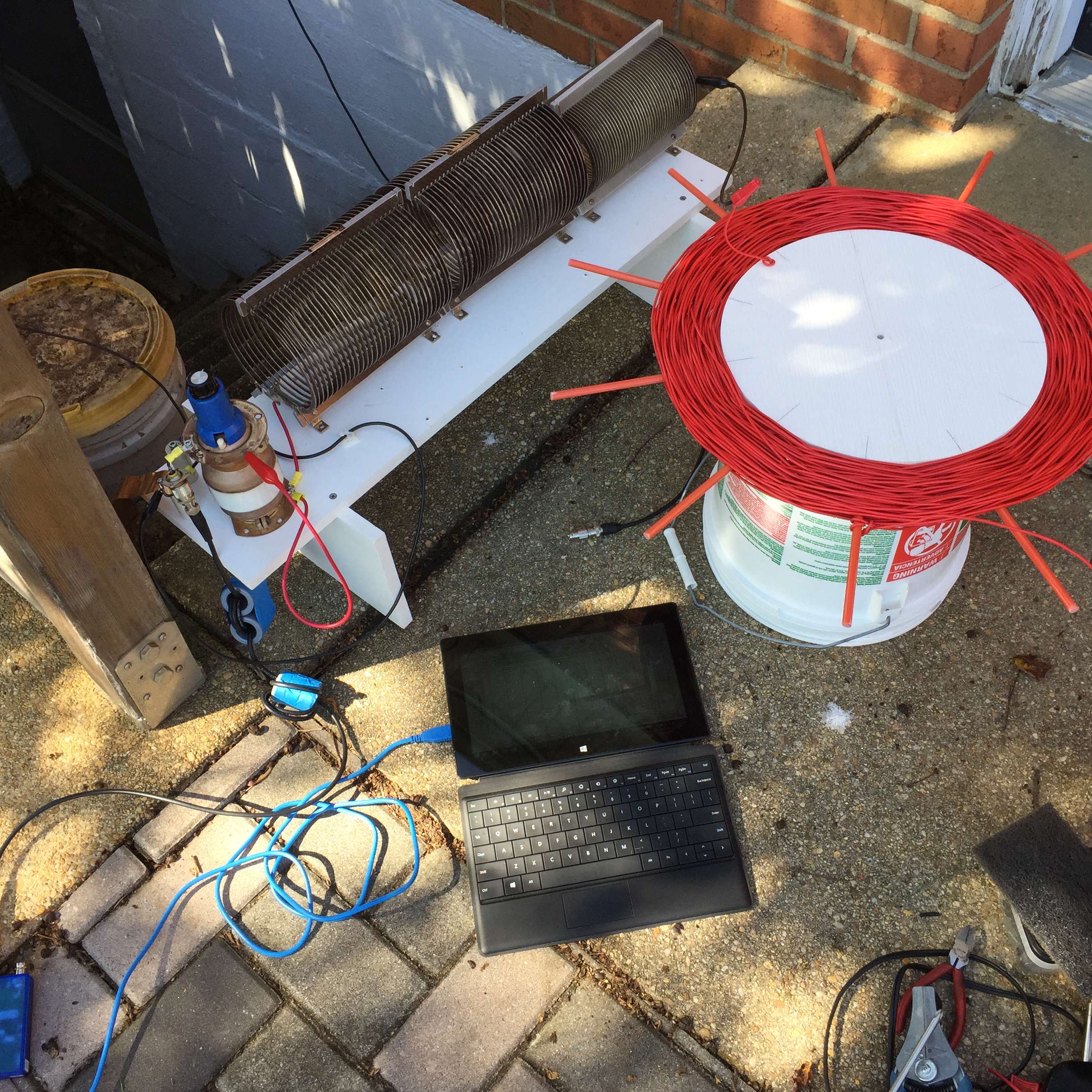
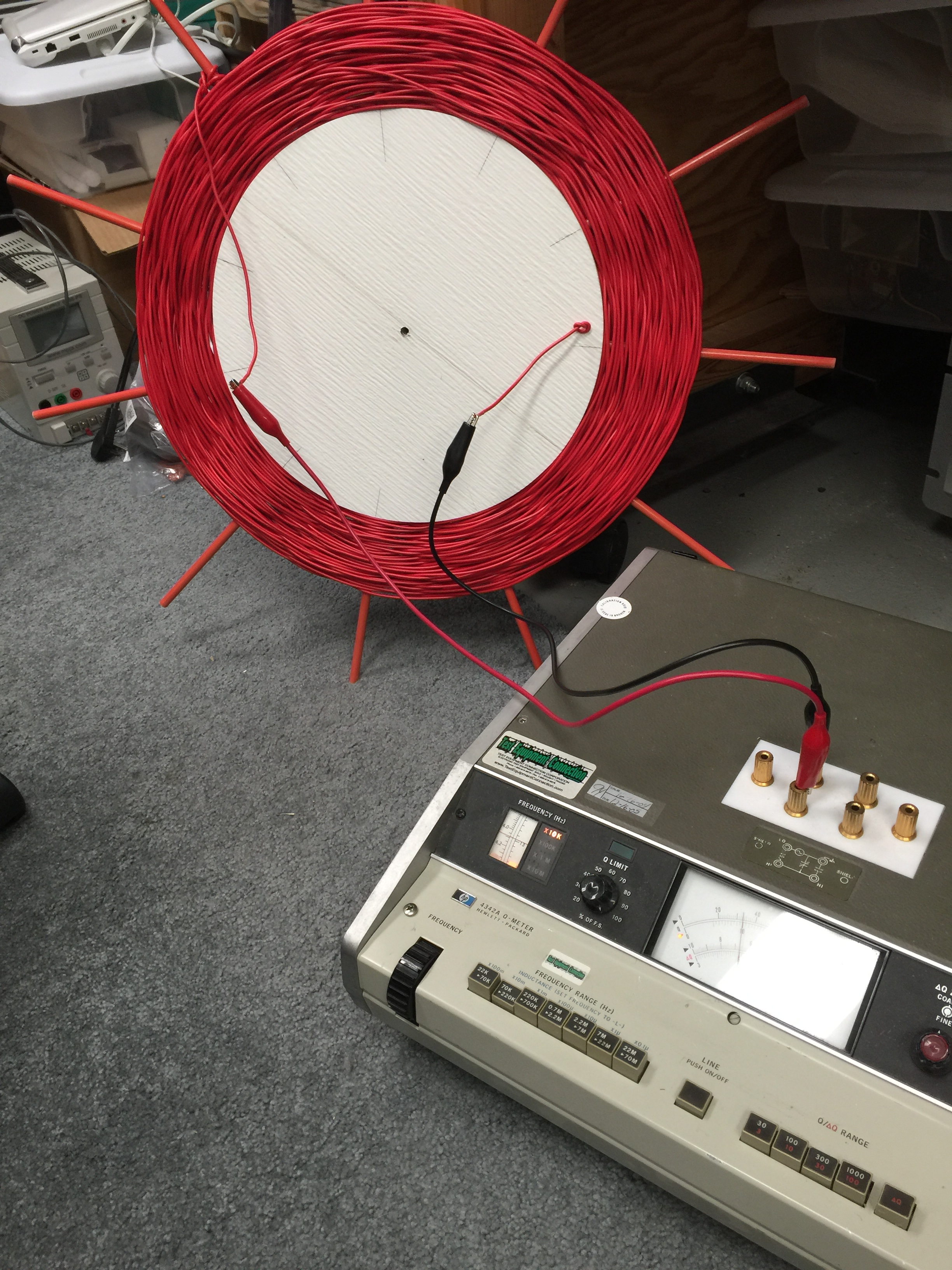
Here is that inductor being tested with a 150 foot long wire. Air coils in the background added to the adjustment. The capacitor is bypassed. |
|
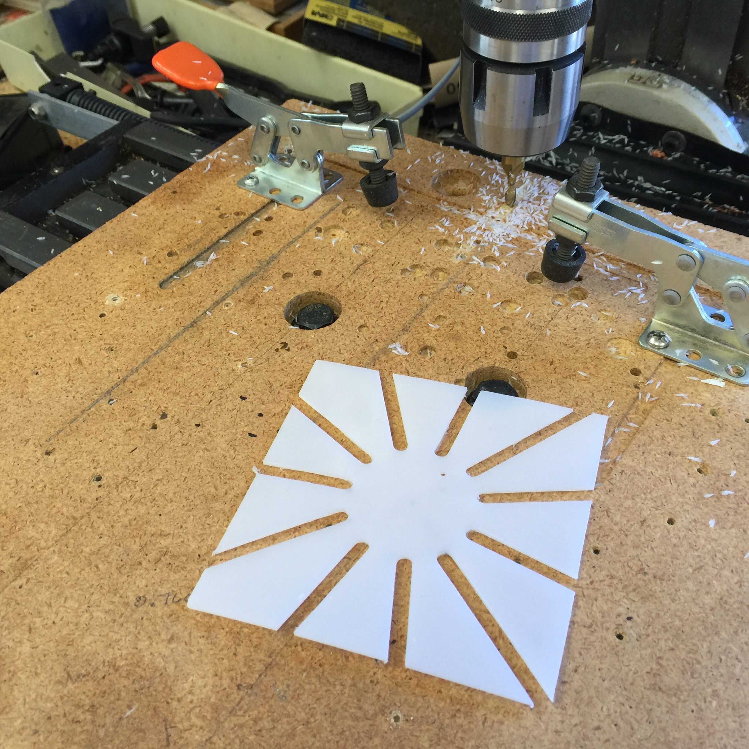
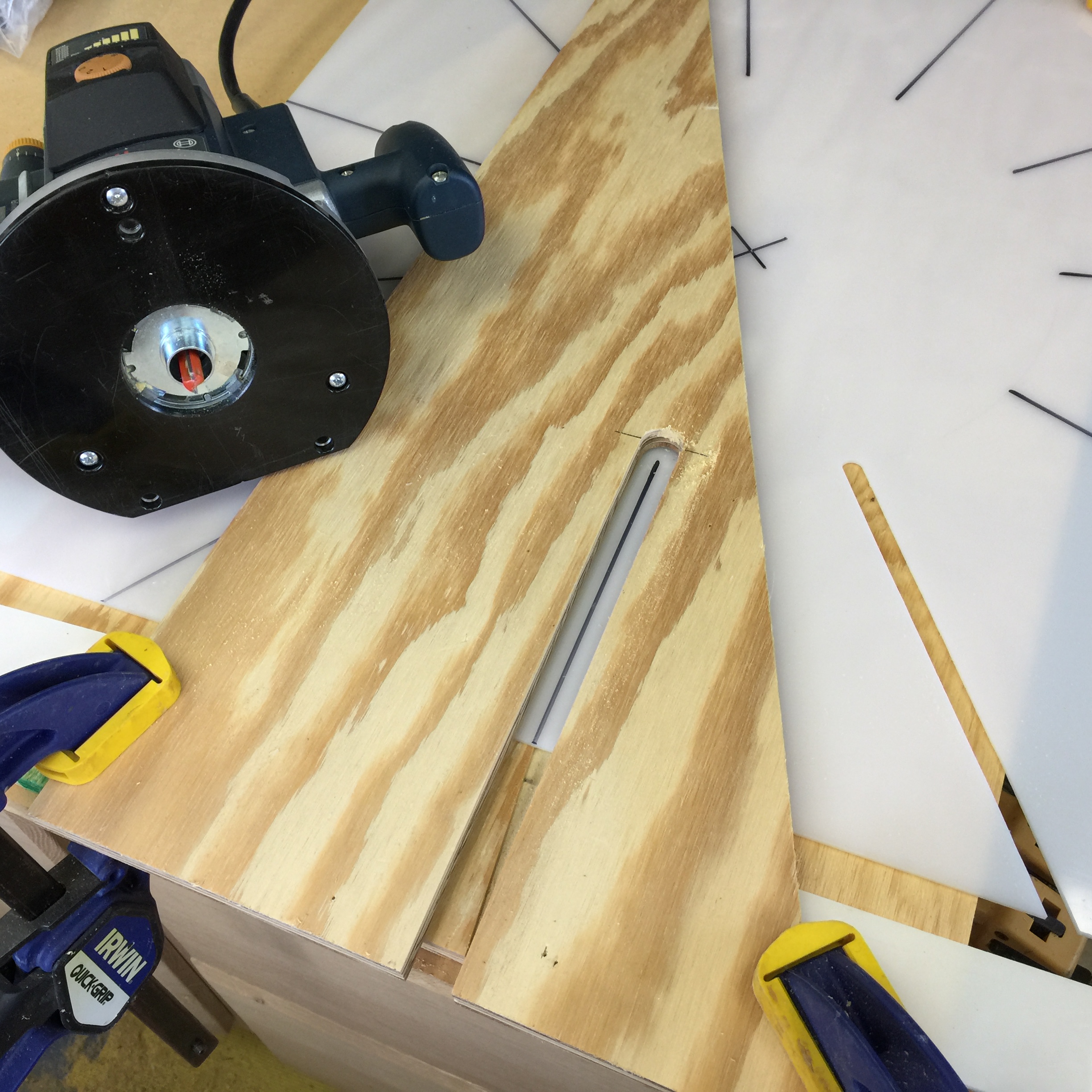
This is the new form, rather than the fiberglass sticks above. Form is 4 inches by four inches and will be used in an elliptical band pass filter for 2200 meters. |
|
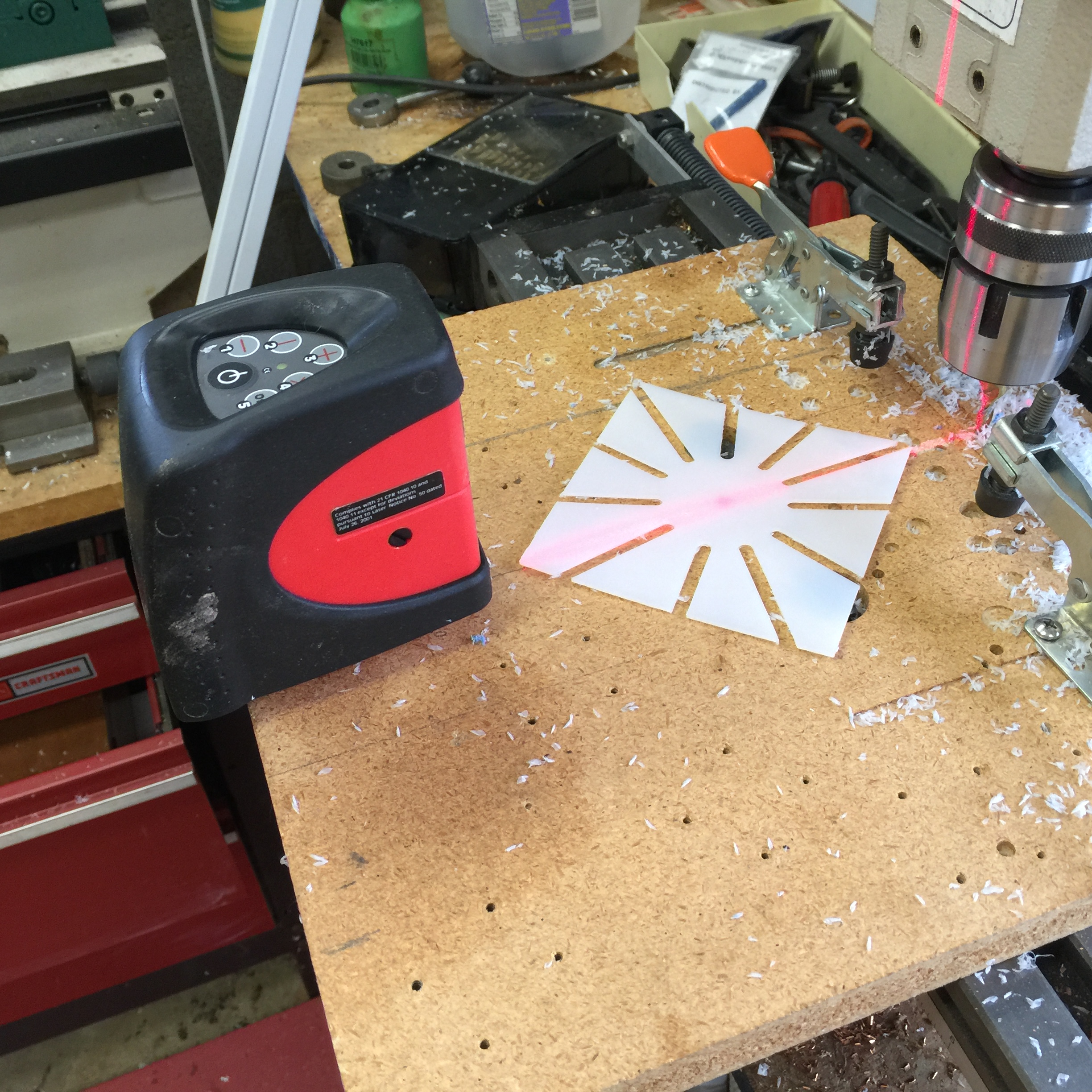
End mill to the right, laser level on the left for alignment. I can “groove” four of the above forms at the same time. |
|
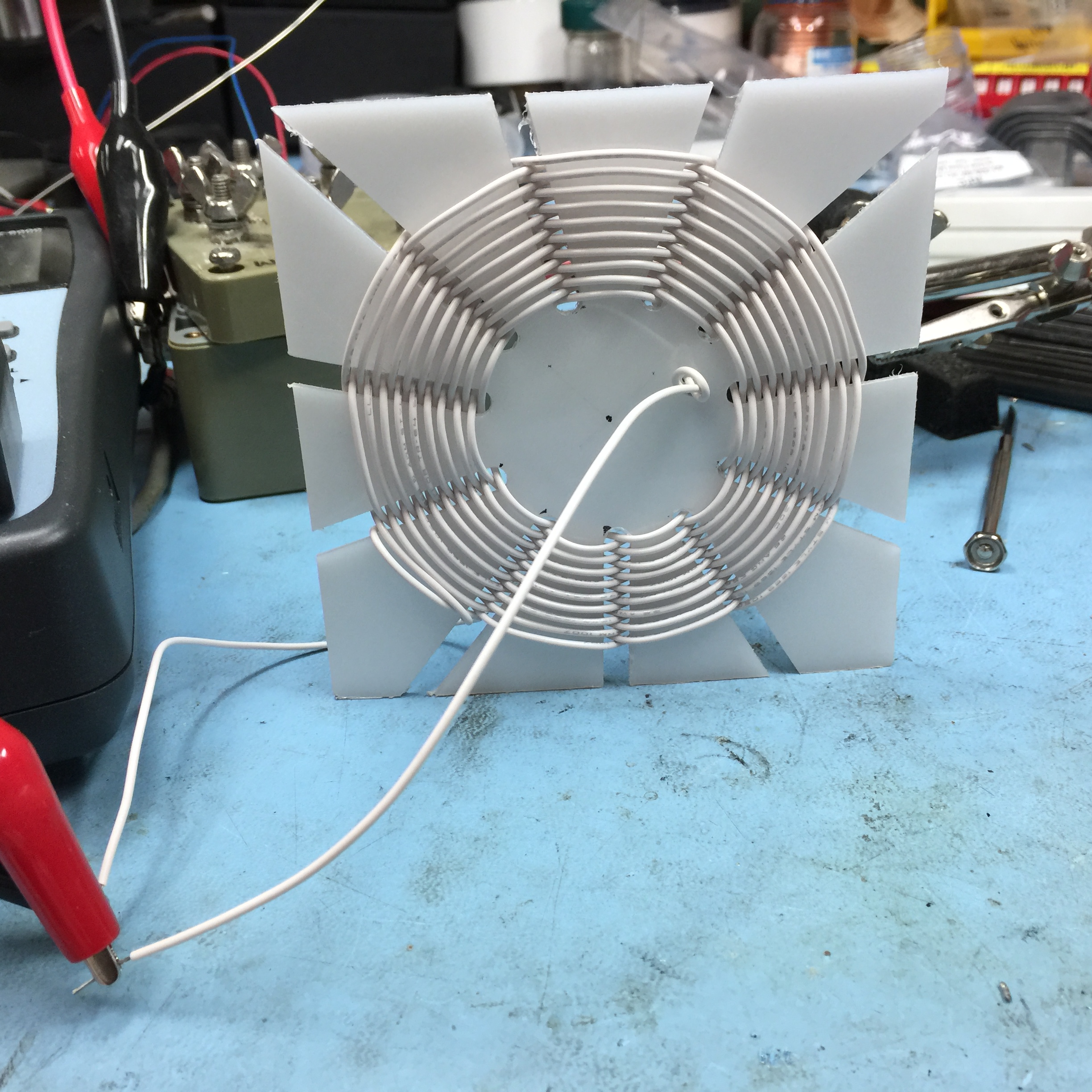
Form wound with simple #20 hookup wire. This one is about 12uH, Q of 50. Q of 220 with 108/40 Litz wire. |
|
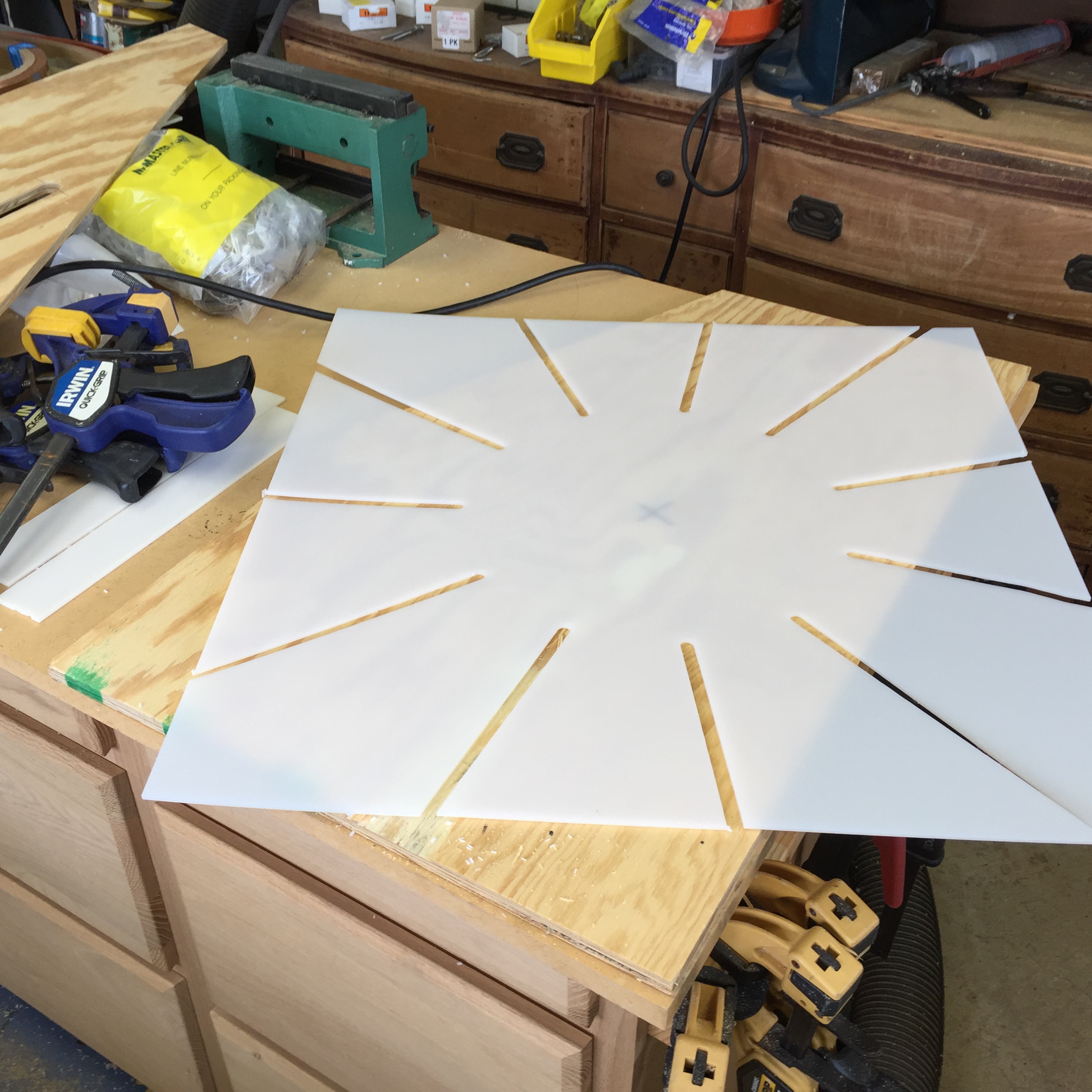
Mechanical set up for a 24 x 24 inch form. Pretty much self explanatory. |
|
Final for the large form. Took about an hour for the first one. Should be able to do two at a time later. |
|
First winding attempt. Inductance was about 3.7 mH and a Q of about 200 at 100kHz. |
|
Spiral Inductor Adventure
The following is a pictorial summary of my spiral inductor development. A simple Spiral Inductor Calculator can be found at: http://www.deepfriedneon.com/tesla_f_calcspiral.html . The spiral inductor mathematics can be found at: http://w5jgv.com/downloads/1937%20NBS%20Circular%20C74%20%28partial%29.pdf (50MB!!) Scroll down to page 204. If this link goes 404, I have it on my machines here and will put it up on my server.
Some of these files are large, give them time to load by clicking on the photo. |
|
Link to Litz wire information: http://www.newenglandwire.com/products/litz-wire-and-formed-cables . See navigation column on the left. |
|
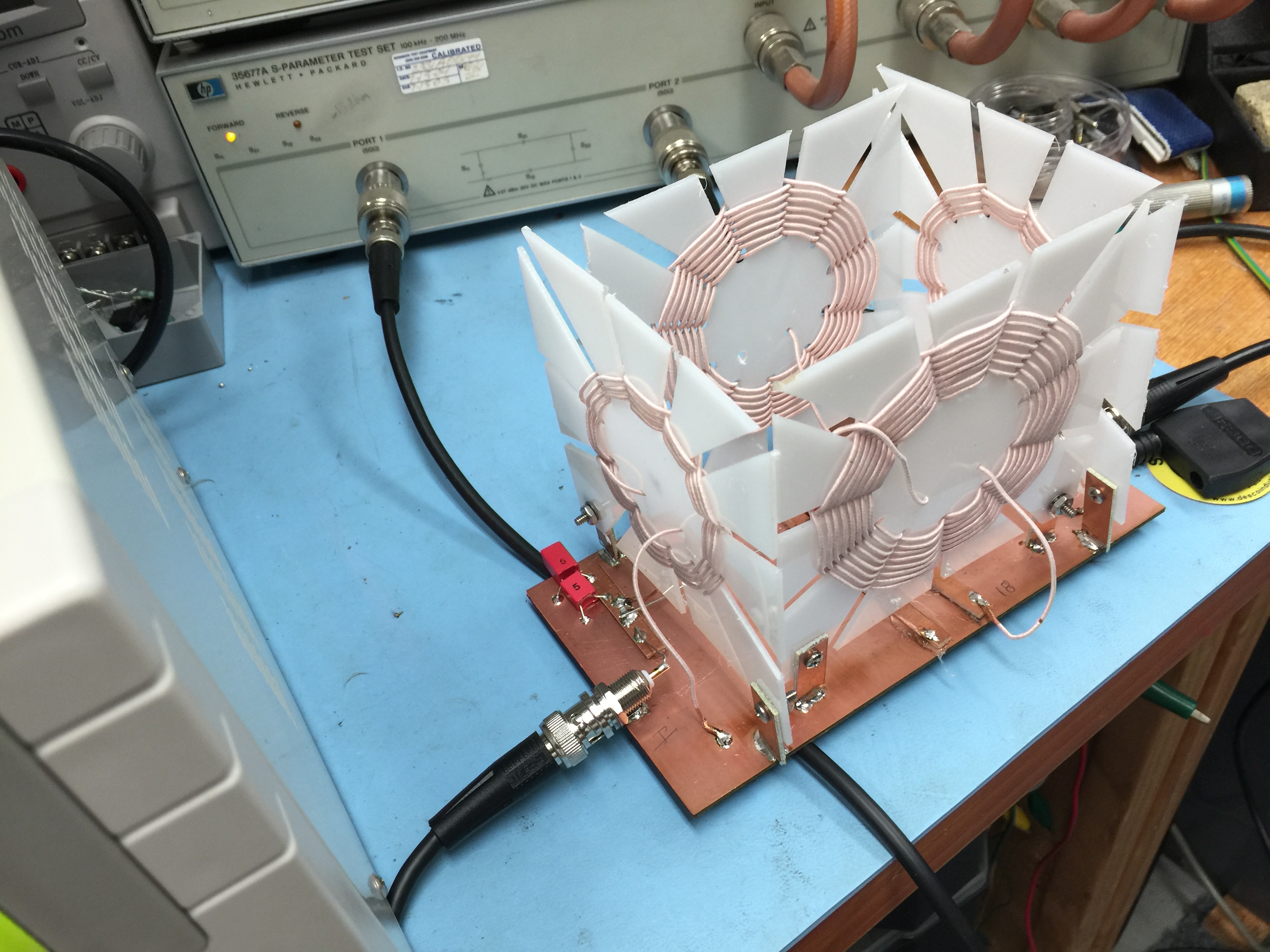
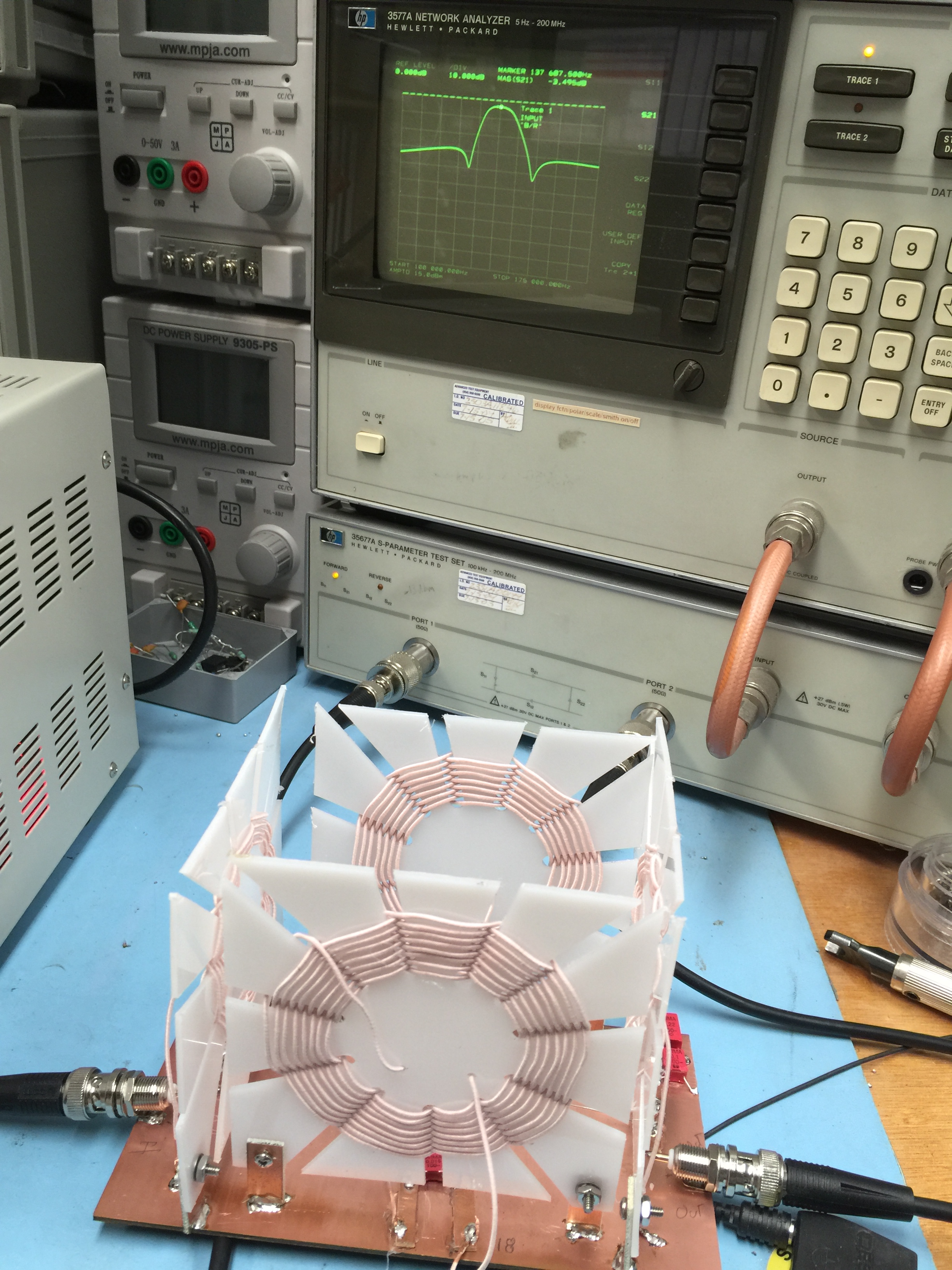
137.5 KHz Elliptical (Cauer) Band Pass Filter, made of four 4x4 inch spiral inductors as shown above. I threw it together in a coupla hours and obviously needs some refinement. But it works. |
|
Another view. |
|
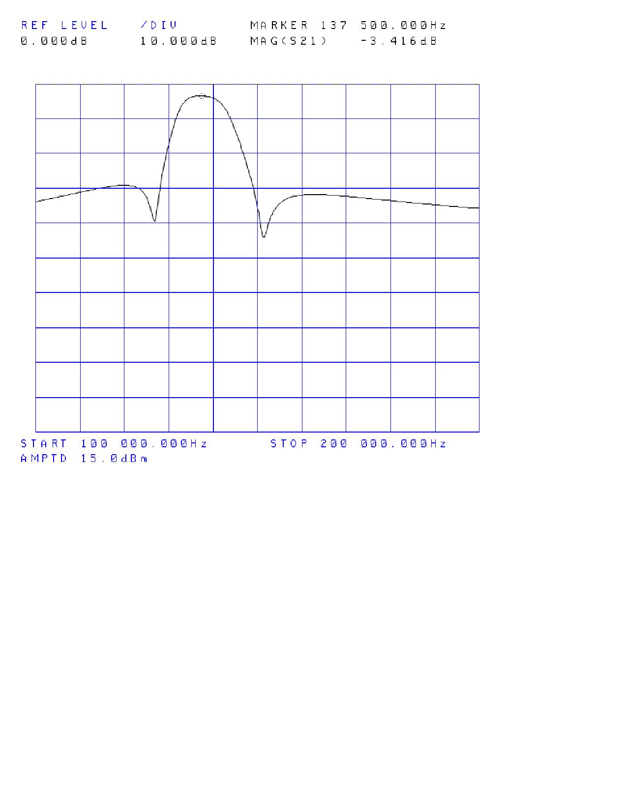
S21 of the filter. I got lazy and two of the forms inner diameter is too large, thus lowering the Q and causing a few dB of extra loss. But 3.4 dB ain’t bad. |
|
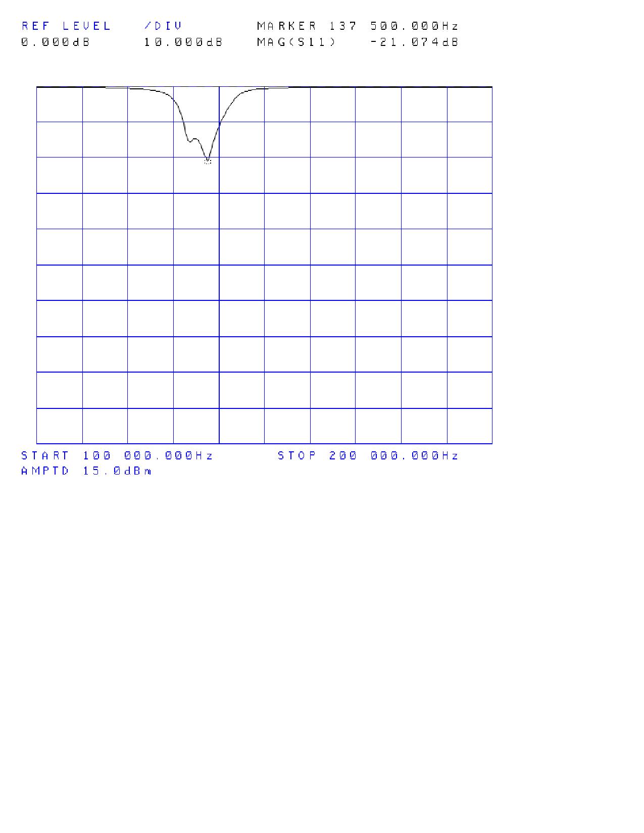
S11 of the filter. The two above mentioned two spirals need tweaked. But not bad with a return loss of 22 dB. Next time I’ll try for greater attenuation in the stop band. Really need to figure out how to package it. |
|
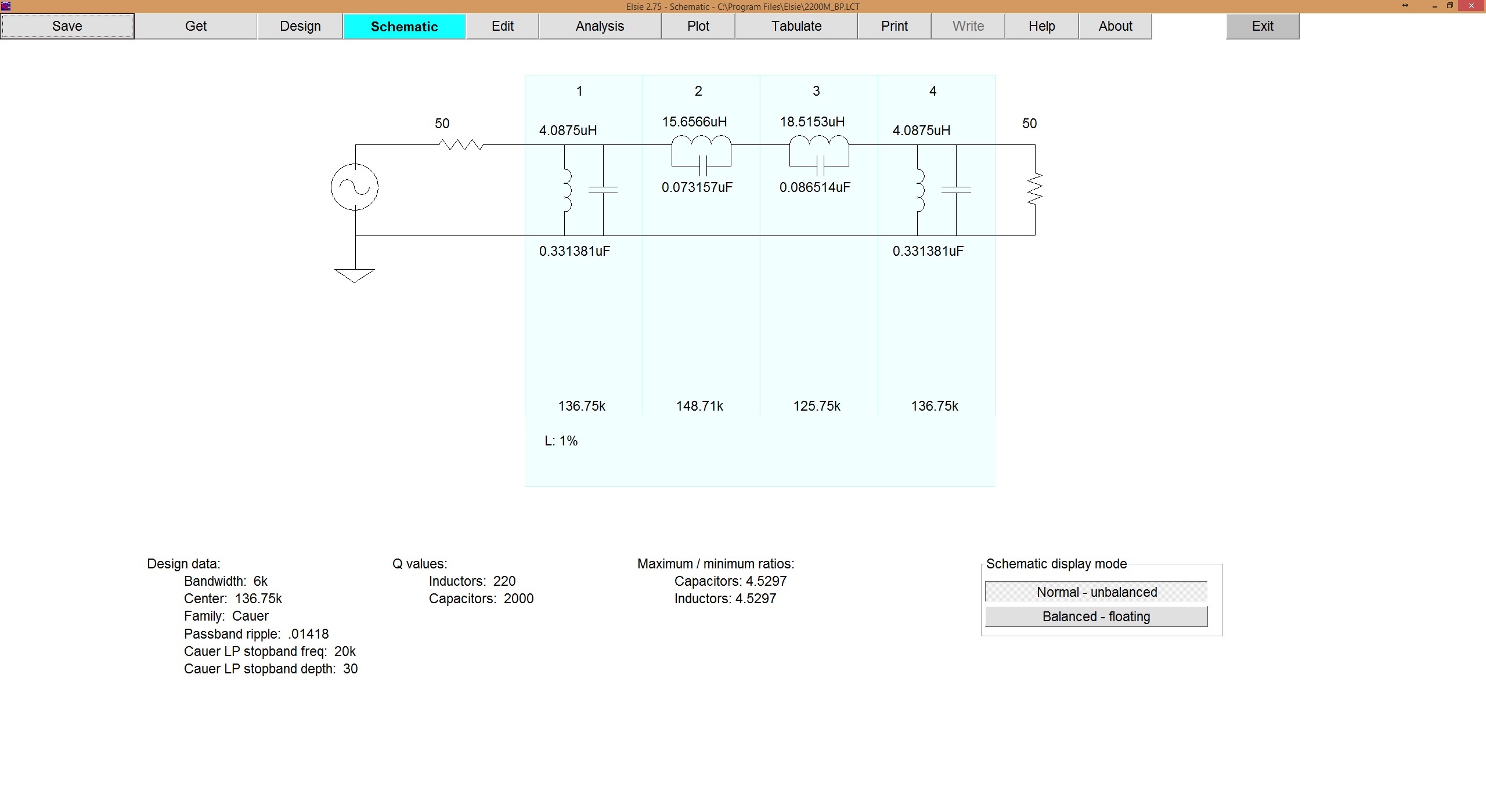
2200 Meter Band Pass Filter Schematic. To get a copy of schematic: Click on thumbnail to the left. File/Save As/ give it a name. Then open in Paint. Print from paint. |